

Airplane stencil evaluation

Pick the airplane construction that survives as a stencil

Airplanes live or die on construction and scale. Compare the jet side-profile, propeller plane, vintage biplane, and minimal paper plane, vet thin wings, fuselage, tail, and contrail holds at your exact width, then prepare a clean stencil that transfers as one readable profile.

Built for working artists preparing airplane pieces. This page covers airplane construction choice, thin-line vetting, and exact-size transfer prep only. Generic photo conversion, Fit to Body mechanics, mirror and export steps, broad gallery browsing, and space motif depth stay in their specialist owners linked below.

What makes an airplane stencil-viable

Construction, hierarchy, and placement size decide the result.

An airplane is a directional profile with a fuselage spine, wing edges, and a tail. These three pillars predict whether that profile survives reduction, print, and transfer.

Construction choice

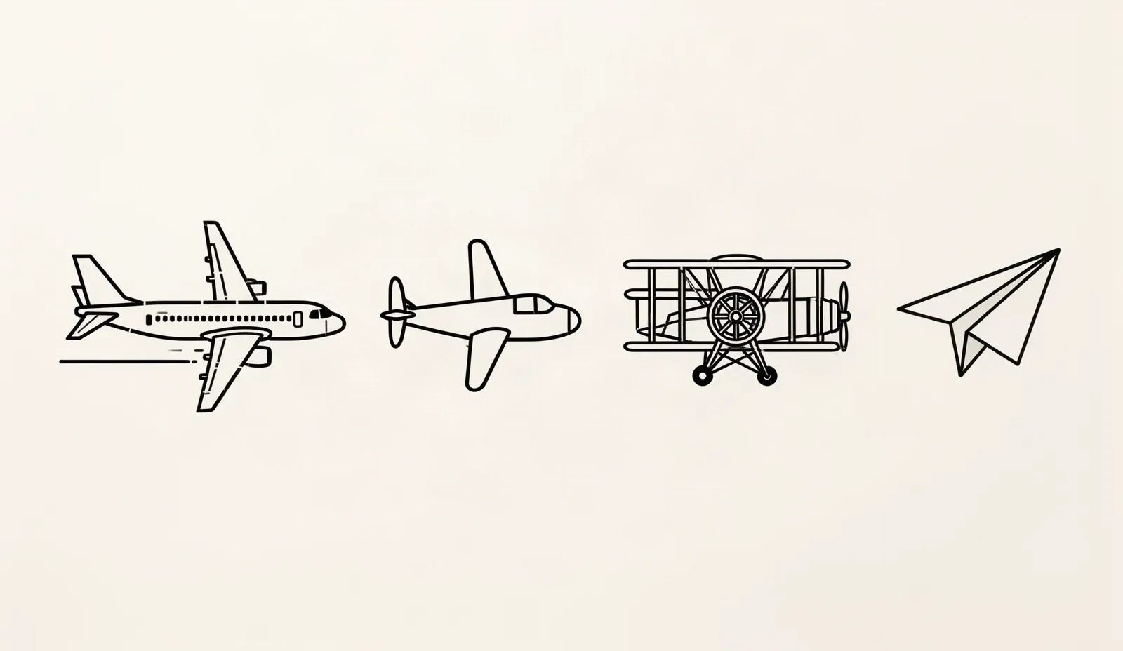
An airplane reads as one of four stencil constructions: commercial jet side-profile with a long fuselage and swept wings, propeller plane with a blunt nose and visible propeller, vintage biplane with stacked wings and struts, or minimal paper-plane outline with folded facets. Stencil viability comes from committing to one construction, not from mixing jet length with biplane struts and a paper-plane tail on one reference.

Check: Name the construction in one sentence before judging detail. If the reference mixes a jet fuselage with propeller blades and biplane struts, pick one construction first. Mixed anatomy cannot be fixed with line weight.
Silhouette and line hierarchy

The outer silhouette (fuselage spine, wing leading edges, tail fin) must stay continuous at final size, while interior marks (windows, panel lines, propeller blades, contrails) stay subordinate. When windows crowd the fuselage, struts close the wing gap, or a contrail competes with the tail, the transfer prints one merged mass and the airplane read goes with it.

Check: Rank every mark as structure, support, or removable at true size. If an interior mark touches or bridges two structural lines, it needs simplifying or removal before print.

Placement-size role

A long horizontal jet needs a long placement axis, while a compact biplane or paper plane fits short or curved fields. The same wingspan succeeds or fails depending on the body length available and the direction the nose points along the limb or torso.

Check: Set intended width in millimeters and the nose direction along the body axis first. If the wingspan overruns the placement or the tail crosses a joint crease, reselect the construction or resize before touching line mass.

Airplane evaluation framework

Score the reference in minutes, then act on the weakest check.

Four airplane constructions at labeled widths. Each one names the protected structure, the fix, and the go or no-go verdict at that exact size. Confirm with a measured 1:1 print.

Four airplane stencil constructions drawn as black linework: a commercial jet in side profile with a short trailing contrail, a blunt-nose propeller plane, a vintage biplane with stacked wings and struts over open skin, and a folded paper plane.
Construction comparison, not a size-calibrated stencil. Illustrative linework made for this guide: jet side-profile with one contrail, blunt-nose propeller plane, stacked-wing biplane with open inter-wing skin, and folded paper plane. Set your own measured width before judging any gap at 1:1.

HOLDS AT STATED SIZE

Commercial jet side-profile at 12 cm

Intended width 120 mm

Source
Long fuselage in clean side-profile with swept wings, single tail fin, simplified window band as one broken strip, and one short contrail trailing the tail.
Protect
Unbroken fuselage spine from nose to tail, swept wing leading edges, tail fin silhouette, and the single window strip treated as one subordinate band.
Fix
Shorten only the contrail tip if it crowds neighboring skin at 1:1. Keep fuselage length, wing sweep, and tail fin unchanged.
Candidate stencil
Same airplane with the construction set, detail count adjusted, and protected contours kept at transferable mass.
Final-size verdict
Holds at 12 cm after a contrail-spacing check. Every structural line stays separate at 1:1 and the jet reads as one directional profile.

SIMPLIFY PROPELLER FIRST

Propeller plane at 10 cm

Intended width 100 mm

Source
Blunt-nose propeller plane with a two-blade propeller disc, cockpit glass, wing strut lines, and small landing-gear marks under the fuselage.
Protect
Blunt nose plus propeller hub as the read anchor, fuselage spine, and the single strongest wing edge on each side.
Fix
Reduce the propeller to one hub with two clean blades, remove landing-gear marks below 10 cm, and merge cockpit glass into one shape. Do not thicken blades to save the gear.
Candidate stencil
Same airplane with the construction set, detail count adjusted, and protected contours kept at transferable mass.
Final-size verdict
Not stencil-ready until the propeller and underside simplify. Gear marks and extra blades close first at this width.

REOPEN WING GAPS

Vintage biplane at 11 cm

Intended width 110 mm

Source
Stacked upper and lower wings with four struts, tail skid, radial engine marks on the nose, and fabric rib lines across both wings.
Protect
Stacked-wing silhouette with visible open skin between the wings, strut rhythm, and the tail assembly direction.
Fix
Cut struts to the two strongest pairs, remove rib lines inside the wings, and confirm open skin runs between the wings from edge to edge at 1:1.
Candidate stencil
Same airplane with the construction set, detail count adjusted, and protected contours kept at transferable mass.
Final-size verdict
Holds at 11 cm once the inter-wing gap stays open at true size. Strut count and rib detail are the variables, not overall width.

ENLARGE OR KEEP MINIMAL

Minimal paper plane at 6 cm

Intended width 60 mm

Source
Paper-plane outline with folded facet lines, small trailing motion marks, and a dotted flight loop behind the tail.
Protect
Single folded outline with one center crease as the read anchor, plus the nose point direction.
Fix
Keep one center crease and remove secondary facets and the dotted loop at 6 cm, or enlarge past the point where each facet transfers as its own line. Do not keep all facets with hairline mass at this width.
Candidate stencil
Same airplane with the construction set, detail count adjusted, and protected contours kept at transferable mass.
Final-size verdict
At 6 cm the extra facets function as broken scratches. Simplify to one crease or enlarge for the full folded construction.

Spacecraft, rockets, and astronaut scenes stay out of this framework. This guide judges stencil-built airplanes with readable wings, fuselage, and tail hierarchy, not space or rocket art. Planet, rocket, and astronaut motif depth stays on the space owner, and broad visual browsing stays on the stencils and subject hubs.

Wings, line weight, and gaps at final size

Judge the white space at the width you will print.

Screens forgive crowding that paper and skin do not. Set the width first, then inspect each feature below at true physical size with scaling off.

About 6 cm and below

Wrist and ankle accents, behind-ear adjacent skin, finger-adjacent panels, and small gap pieces.

Carry one construction with a single outline family and one interior band maximum. Paper-plane minimal or a shortened jet profile works here; biplane stacks and full propeller assemblies do not survive without a recrop.

About 8 to 13 cm

Common forearm and calf panels, outer arm runs, and shoulder-to-chest transitions.

The most flexible band. A jet side-profile, a simplified propeller plane, or a reduced biplane can work when every wing gap and window band is verified at true size. Check strut count and propeller blades before approving line mass.

About 14 cm and above

Thigh compositions, upper back panels, and full side-torso runs.

Room for a full jet profile with a window strip plus contrail, or a complete biplane with struts, but only when open skin separates wings, tail, and fuselage details from edge to edge. Larger width does not rescue mixed constructions or closed wing gaps.

Airplane feature checks by width band
FeatureAbout 6 cm and belowAbout 8 cm and above
Outer fuselage, wing, and tail contoursKeep the heaviest lines here. If a wing leading edge or tail fin disappears, the airplane loses its direction and becomes a plain dart.Same priority. Larger width allows slightly finer outer contours, but separability still beats uniform thinness.
Windows, panel lines, and propeller bladesCarry at most one simplified band or blade pair, each with visible skin around it. Repeated window dots and extra blades merge first at small widths.A broken window strip or two-blade propeller can work when each mark keeps its own clearance. Check the full set with a squint test at true size.
Struts, wing gaps, and contrailsKeep one open wing gap or one short contrail maximum. Secondary struts and long looping trails compete with wing separations for the same room.One secondary strut pair or one trailing contrail can add depth when the primary silhouette clearly dominates. Equal-weight trails need hierarchy work before print.
Nose direction and flight flowKeep one unbroken nose-to-tail direction. Reversed or looping flight paths crowd small fields and should be recropped away.One gentle curve along the limb or torso adds movement when the nose direction clearly dominates. Competing curves need hierarchy work before print.

Reference to clean stencil

Build along the fuselage, from the nose outward.

Work in this order so one change at a time can be judged at the same width. Stop when construction, hierarchy, gaps, and readability each pass.

  1. 01

    Lock width, placement, and construction first

    Set the intended physical width in millimeters, name the body area, and commit to one of the four constructions before judging the reference. A jet profile that holds at 14 cm on a thigh can fail at 6 cm on a wrist with no line being wrong on its own.

  2. 02

    Verify silhouette and rank the line hierarchy

    Trace the fuselage spine, wing leading edges, and tail fin as structure, rank windows, blades, struts, and contrails as support, and mark one removable detail that can go if gaps close. Resolve mixed constructions and equal-weight competitors before touching line weight.

  3. 03

    Simplify thin holds at 1:1

    Reduce window counts, propeller blades, struts, and contrail length before thinning contours. Keep open skin between stacked wings, confirm each separation runs to open air, and run a squint check: step back until interior detail disappears and confirm the fuselage, wings, and tail still read as an airplane.

  4. 04

    Run the small-size readability test

    Print at the exact width with scaling off and check the narrowest wing gap, the smallest window separation, and the thinnest tail or contrail line. If a gap closes or a line breaks on plain paper, enlarge, recrop, or simplify the construction rather than forcing reduction.

  5. 05

    Verify exact-size print and transfer path

    Export a true-size PDF with no fit-to-page scaling, inspect the narrowest separations on plain paper, then measure the physical print with a ruler. If the digital file passes and only paper fails, move to print-stage evidence instead of simplifying again.

Placement and flight-direction decisions

Airplanes want skin that gives the nose a direction

An airplane is a directional profile. Placements with a clear long axis preserve the flight read with little compensation, while tight curved spots demand a compact recrop.

Outer forearm and calf

Long fields where a jet side-profile or propeller plane should fly along the limb. Wings pointing hard across the limb wrap fast and crowd the trailing edge.

Check: Point the nose along the limb axis and shorten cross-limb wing tips while edits are still cheap.

Thigh and upper back

Broad panels with room for a full jet profile with contrail or a complete biplane stack. The most forgiving area for longer wingspans.

Check: Lay the wingspan along the longest available span, then confirm every wing gap keeps open skin at 1:1 before print.

Ribs and side torso

Vertical fields that suit a climbing airplane angle, but breathing movement and side curvature punish wide horizontal spreads.

Check: Keep the composition slim with a rising nose angle, and preview the stencil on a torso photo before locking width.

Wrist, ankle, and small gaps

Tight curved spots where only a compact paper plane or shortened jet nose survives. Full biplane stacks forced into these spots merge first.

Check: Recrop to the strongest single outline with the widest wing gap, then run the small-size checks at the exact width.

Stencil-ready checklist

Approve the airplane only when every line passes

Run this short sequence with scaling off and a ruler in hand. One failed line means fix, enlarge, or reselect before transfer.

  • Confirm intended width in millimeters, the named placement, and one committed airplane construction.
  • Confirm an unbroken fuselage spine, wing leading edges, and tail fin at 1:1.
  • Confirm every wing gap and strut separation runs to open air at true size.
  • Confirm windows, blades, and contrails read as subordinate marks, not competing structure.
  • Confirm nose direction follows the body axis without crossing a joint crease.
  • Export a true-size PDF with scaling off and measure the physical print.
One construction leads Verify gaps at 1:1 Nose follows placement

FAQ

Airplane stencil decisions, answered

Short answers for the construction, gap, weight, and placement checks that recur when an airplane reference moves toward transfer-ready output.

Judge by available length and width. Commercial jet side-profiles suit long forearm, calf, thigh, and back runs where fuselage length is an asset. Propeller planes suit medium panels where a blunt nose and propeller read fast. Vintage biplanes suit square-ish fields with room for stacked wings and open inter-wing skin. Minimal paper planes suit wrists, ankles, and small gaps where only one outline and one crease survive. This page recommends committing to one construction before judging line weight.

Next steps

Use the neighboring owners for adjacent jobs.

This guide covers airplane construction choice, width-tied wing and window gap rules, flight-aware placement, and reference-to-stencil preparation. Use the links below for related jobs such as sizing, print checks, paper, and placement.

Board organization, grid overlays, photo-quality scoring, generic conversion, Fit to Body mechanics, broad gallery browsing, paper manufacturing detail, and space motif depth stay in their specialist owners. The links above hand off instead of repeating that detail.

From evaluated reference to working stencil

Turn the approved airplane into a stencil draft.

Start from the airplane that passed the construction and gap check, then continue on iPhone for body fit, exact-size print, mirror and professional export.