

Biomechanical stencil vetting

Judge any biomechanical reference before it becomes a stencil

Biomechanical work lives or dies on the machine versus flesh read. Vet piston and plate structure against the tearing edge, convert layered depth into bridge-safe lines, then plan tears and wrap sizing at your exact width.

Built for working artists preparing biomechanical pieces. This page covers first-read vetting, depth-to-bridge conversion, tear and break planning, and muscle-flow placement only, not tattoo application or healing advice.

What makes biomechanical work stencil-viable

First read, bridges, and breaks decide the result.

A biomechanical composition is machine structure set inside torn flesh and worn on moving muscle. These three pillars predict whether that interweave survives reduction, print, and transfer.

Machine versus flesh first read

A biomechanical piece reads as machine parts set inside torn flesh: pistons, ribs, plates, and cables on one side, skin edges and muscle on the other. The stencil works when one side leads at a glance and the other supports it. When both sides carry equal density, the transfer reads as gray noise from a normal viewing distance.

Check: Squint at the reference until fine detail disappears. If pistons or plates still read as one structure and the tearing edge still reads as a second structure, the hierarchy is sound. If both dissolve into one patch, the reference needs ranking before any bridge work.
Depth converted to bridges

Reference art builds depth with layered shading, overlapping plates, and repeating rib or piston rows. A stencil builds depth with separated lines and open skin between them. Every shaded pocket that should stay open needs a bridge: a deliberate line that holds the surrounding structure apart so the gap survives print and transfer.

Check: Cover all shading on the reference. If the piston rows, rib stack, and plate edges still read as separate marks with visible skin between them, the line structure carries the depth. If the read depends on the shading, that depth must be rebuilt as spacing before print.

Tearing edges and motion breaks

Torn flesh edges and open-skin breaks are what keep a biomechanical transfer on the body. Long unbroken mechanical bands crack visually across joints and high-motion muscle, while tearing edges placed along the motion direction let the piece flex. Open skin inside the composition is structure, not empty space.

Check: Trace each long mechanical run on the reference. If it crosses a joint or a flexing muscle belly with no tear or skin break inside it, plan one before print. Verify breaks on a live body preview while edits are still cheap.

First-read vetting framework

Score the reference in minutes, then act on the weakest check.

Four biomechanical constructions at labeled widths. Each one names the protected structure, the fix, and the go or no-go verdict at that exact size. Confirm every verdict with a measured 1:1 print.

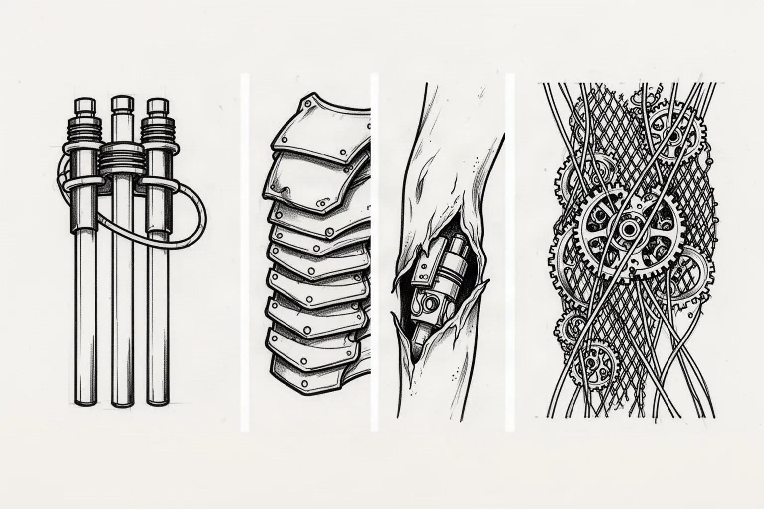
Four-panel black linework study: a piston cluster with open channels between rods, layered plates separated by open gaps, a torn flesh edge opening over a curved limb with a mechanical segment beneath, and a dense micro gear and mesh field with almost no open space.
Original illustrative linework study, not app output and not a measured stencil. Panels show the four constructions judged below: open-channel piston cluster, separated plate stack, tearing edge on a curved limb, and over-dense micro gear detail. Confirm every verdict on your own measured 1:1 print.

HOLDS AT STATED SIZE

Piston cluster with open channels at 12 cm

Intended width 120 mm

Source
Three parallel piston rods with ring collars, one cable loop, and a single torn edge along one side. Rods run in one direction with visible channels between them and no second shading system competing for the same room.
Protect
The rod direction, the collar positions, the open channels between rods, and the single torn edge location.
Fix
Adjust nothing structural. Confirm each inter-rod channel stays open at 1:1 and keep collar detail to one ring line per collar.
Candidate stencil
Same composition with the machine structure ranked, channels separated, tear plan set, and micro detail reduced for the stated width.
Final-size verdict
Holds at 12 cm. Rods read as machine, the torn edge reads as flesh, and every channel survives true-size inspection.

REBUILD THE SPACING

Layered plates with merged shading at 10 cm

Intended width 100 mm

Source
Attractive stacked plate composition with repeating rib rows underneath, but plate shadows touch rib edges and neighboring plates share edges with no skin between them. Strong on screen, one connected mass at transfer size.
Protect
The plate overlap order, the rib direction, and the single strongest plate edge as the rebuild anchor.
Fix
Separate every plate edge with open skin, reduce rib rows to the count the width can carry, and convert one shading pocket per plate into spacing instead of tone. Do not thicken plate outlines to compensate for touching edges.
Candidate stencil
Same composition with the machine structure ranked, channels separated, tear plan set, and micro detail reduced for the stated width.
Final-size verdict
Not stencil-ready until plates and ribs separate at true size. Outer drama cannot compensate for merged structure.

PLAN TEARS BEFORE PRINT

Full-wrap mechanical band at 18 cm with no breaks

Intended wrap length 180 mm

Source
Continuous mechanical sleeve band with pistons, mesh, and cabling running unbroken around the limb. Complete object, but no tearing edge or open-skin break interrupts the band, and both ends meet without a planned closing joint.
Protect
The piston direction, the cable path, and the wrap circumference measured on the limb.
Fix
Insert two tearing edges along the muscle direction and one open-skin corridor where the wrap closes. Angle long rods with the muscle flow and mark registration ticks on the stencil margin before transfer.
Candidate stencil
Same composition with the machine structure ranked, channels separated, tear plan set, and micro detail reduced for the stated width.
Final-size verdict
Holds at 18 cm only after tear and closing-joint planning. An unbroken mechanical ring fights every joint and flex line it crosses.

ENLARGE OR RECROP

Fine micro-gear detail that plugs at 5 cm

Intended width 50 mm

Source
Delicate gear teeth, fine mesh, small screws, and thin cable strands packed around a small piston core. Detailed on screen but drawn with almost no line mass and seven competing micro bands.
Protect
The piston core direction and the single gear position that gives the piece its machine read.
Fix
Enlarge past the point where gear teeth and mesh transfer as separate marks, or recrop to the piston core with one gear and one cable. Do not keep mesh plus screws plus micro-cables together at 5 cm.
Candidate stencil
Same composition with the machine structure ranked, channels separated, tear plan set, and micro detail reduced for the stated width.
Final-size verdict
At 5 cm the micro detail functions as one band and fine channels print closed. Enlarge, recrop, or choose a bolder construction for this width.

Weapon-form silhouette choice stays with the gun owner. Graffiti skeleton and drip conversion stays with the graffiti owner. Axis and symmetry vetting stays with the geometric and cybersigilism owners. Broad visual browsing stays on the stencils and subject hubs. This framework exists to judge biomechanical first read, bridge-safe conversion, and tear planning at a stated width, not to replace those owners.

Mechanical detail at final size

Judge the channels at the width you will print.

Screens forgive crowding that paper and skin do not. Set the width first, then inspect each feature below at true physical size with scaling off.

About 8 cm and below

Small panels, gap fillers, and single-motif accents.

One piston or plate group maximum with a single torn edge. Keep one line family and two separations. If any inter-part channel or tear gap closes at 1:1, enlarge or reselect rather than forcing reduction.

About 8 to 16 cm

The common biomechanical band: forearm panels, calf work, shoulder caps, and chest sections.

The most flexible band. Piston rows plus one rib or plate layer hold when every channel is verified at true size. Confirm rod separation, collar count, and tear placement before approving mesh or cable detail.

About 16 cm and above

Thigh panels, back sections, and full wrap compositions.

Room for layered plates with real rib stacks and multiple tearing edges, but only when open skin separates every layer. Larger size never rescues touching plate edges or an unbroken band across a joint.

Biomechanical feature checks by width band
FeatureAbout 8 cm and belowAbout 8 cm and above
Pistons, rods, and collarsCarry one rod direction with one collar line each. If adjacent rods share an edge, that channel needs reopening before anything else changes.Additional rod rows can work when each channel keeps its own open skin. Collars should never join neighboring rods into one mass.
Ribs and layered platesKeep one rib direction and one plate edge family. Repeating micro-ribs merge first at small widths.Stacked plates can carry real depth when the overlap order is explicit and every edge keeps separation at true size.
Tearing edges and open skinOne torn edge with a clear flesh side and a clear machine side. Thin torn flaps drop out first.Multiple tears can stage the composition, but each tear must end in open skin rather than touching another mechanical mark.
Mesh, cables, and micro detailKeep no mesh field, gear teeth, or screw rows. Object lines and tear gaps compete for the same room and micro detail loses.One mesh or cable family can add depth when it sits inside a protected field with open skin on both sides.

Reference to clean stencil

Rank the read, then build the bridges.

Work in this order so one change at a time can be judged at the same width. Stop when first read, channels, tears, and placement each check out.

  1. 01

    Lock width, placement, and composition first

    Set the intended physical width in millimeters, name the body area, and commit to one composition: piston-led, plate-led, or rib-led with its tearing edge plan. A piston cluster that holds at 12 cm on a flat outer thigh can close the same channels at 6 cm on a curved wrist with no line being wrong on its own. Use the size calculator when target dimensions are still open.

  2. 02

    Rank the machine versus flesh read

    Decide which side leads at first glance and which side supports. Assign every mark a role: machine structure that carries the first read, flesh edges that frame it, and detail that can be removed. A piece with a separated machine structure and one clear torn edge is already halfway to stencil-ready.

  3. 03

    Convert depth into bridges and spacing

    Replace layered shading with separated lines and open skin. Give every shaded pocket that must stay open a bridge that holds the surrounding structure apart, reduce rib and mesh counts to what the width can carry, and keep one removable detail row that can go if gaps close.

  4. 04

    Place tears and breaks at 1:1

    Print at 100 percent with scaling off and run the tear check at arm's length: every long mechanical run gets a tearing edge or skin break before it crosses a joint or flexing muscle, and the wrap closing joint is planned rather than hoped for. Reopen the tightest channel first, then the tightest tear gap. Enlarge the piece when protected structure starts changing shape.

  5. 05

    Verify print and transfer path

    Export a true-size PDF with no fit-to-page scaling, inspect the narrowest inter-part channel and the smallest tear gap on plain paper, then measure the physical print with a ruler. If the digital file passes and only paper fails, move to print-stage evidence instead of simplifying again.

Placement and size decisions

Flat fields preserve plates, wraps demand tear planning

A biomechanical composition is drawn flat and worn on muscle that moves. Flat placements preserve layered plates with little compensation, while wrap placements need tear breaks and closing joints planned in advance.

Outer forearm and calf

Long, fairly stable fields where piston direction can follow the limb axis. The axis becomes the machine direction, so rods leaning across the limb crowd fast.

Check: Run rods and ribs along the limb axis, set the torn edge on the side with the most skin, and confirm every channel at the exact width.

Shoulder cap and outer thigh

Broad curved panels with room for layered plates and rib stacks. The curve compresses one side of flat-drawn plates in photos and transfers.

Check: Center the plate anchor on the flattest span, angle secondary layers with the muscle direction, and verify plate separation at 1:1.

Chest and back sections

Large fields where symmetrical composition tempts equal density on both sides. Equal density on both sides produces the gray-noise read this style is known for.

Check: Pick the lead side before print, keep the support side lighter, and confirm the first read with a squint test at true size.

Full wraps and joint crossings

Compositions that circle a limb or cross elbow, knee, or wrist. Unbroken mechanical bands fight every flex line they cross and the closing joint meets itself.

Check: Insert tearing edges along the motion direction, plan the closing joint with registration marks, and confirm with a dry wrap before transfer.

Stencil-ready checklist

Approve the piece only when every line passes

Run this short sequence with scaling off and a ruler in hand. One failed line means fix, enlarge, or reselect before transfer.

  • Confirm intended width in millimeters, the named placement, and the piston, plate, or rib composition.
  • Confirm the machine side and the flesh side read as two structures in a squint test.
  • Confirm every piston channel, rib gap, and plate separation stays open at 1:1.
  • Confirm every long mechanical run has a tear or skin break before a joint or flex line.
  • Confirm the wrap closing joint is planned with registration marks where the piece wraps.
  • Export a true-size PDF with scaling off and measure the physical print.

Transfer-hold prep

Transfer without plugging the machine

Biomechanical transfers fail at four predictable points. Each one below names the early sign and the prevention that keeps rods, ribs, and tears legible.

Plug-in between rods and ribs

Early sign: Parallel rods or rib rows that looked separated on screen print as one connected band.

Prevention: Judge channels on the measured 1:1 paper print, not the screen. Enlarge the piece or remove one neighboring row when the tightest must-keep channel closes, and re-check after any line-weight increase.

Tear edge dropout

Early sign: Thin torn flaps transfer patchily or vanish while heavy machine masses hold.

Prevention: Draw every torn flap that must survive at working-line mass and anchor each tear to one solid machine edge. Remove flaps the design reads without.

Wrap closing mismatch

Early sign: The final mechanical section overlaps or gaps where the wrap meets itself.

Prevention: Count the composition across the full measured circumference, mark registration ticks on the stencil margin, and confirm the closing joint on the body preview before transfer.

Motion cracking across joints

Early sign: A long unbroken band looks correct on first contact but reads as strained once the joint bends.

Prevention: Break long runs with tearing edges placed along the motion direction and verify the plan on a live body preview with the joint flexed.

Prerequisites before the transfer touches skin

Confirm the measured 1:1 paper print with a ruler, a clean dry placement area, and the planned anchor point (plate anchor for flat panels, lead tear for wraps). Transfer in sections from the anchor so the free end cannot drag channels closed. If the first contact looks faint or patchy, diagnose the layer with the transfer troubleshooter instead of pressing harder.

Open the transfer troubleshooter
Rank machine versus flesh first Verify channels at 1:1 Plan tears before joints

FAQ

Biomechanical stencil decisions, answered

Short answers for the first-read, bridge, tear, and placement checks that recur when a biomechanical reference moves toward transfer-ready output.

It reads when two checks pass at the exact physical size: a squint test still shows machine structure on one side and torn flesh on the other, and every piston channel, rib gap, and plate separation stays open at 1:1. If the read depends on shading rather than separated lines, the reference needs bridge rebuilding before print.

Next steps

Use the neighboring owners for adjacent jobs.

This guide covers biomechanical first-read vetting, bridge-safe conversion, tear and break planning, and muscle-flow wrap sizing. Use the links below for related jobs such as sizing, print checks, paper, and placement.

Gun silhouette choice, graffiti conversion, geometric symmetry, generic sleeve sequencing, board organization, grid overlays, generic conversion, broad gallery browsing, print mechanics, paper manufacturing detail, and placement measurement depth stay in their specialist owners. The links above hand off instead of repeating that detail.

From vetted reference to working stencil

Turn the approved biomechanical piece into a stencil draft.

Start from the composition that passed the first-read, bridge, tear, and placement checks, then continue on iPhone for body fit, exact-size print, mirror and professional export.